|
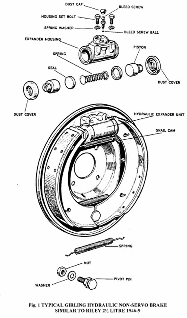
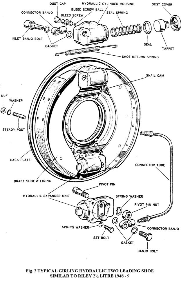
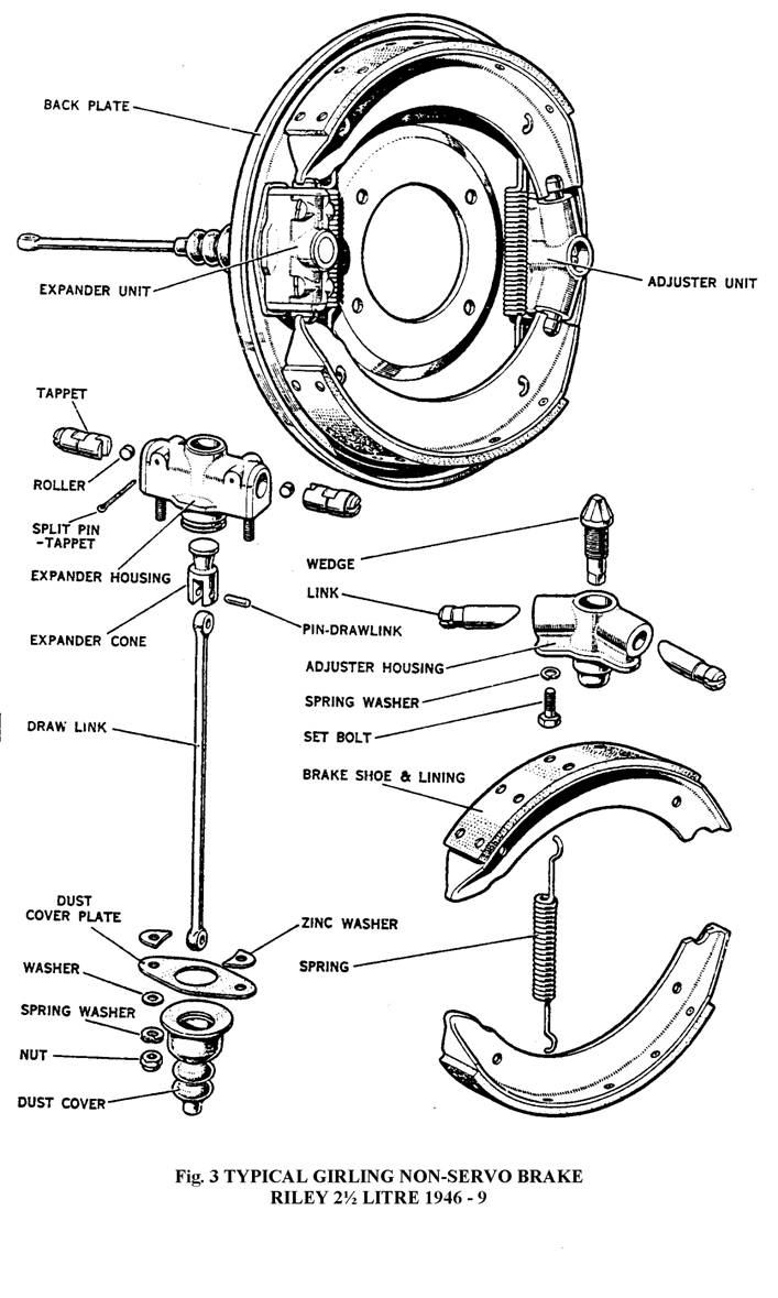
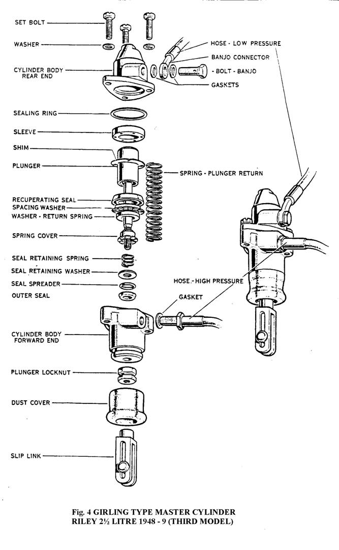
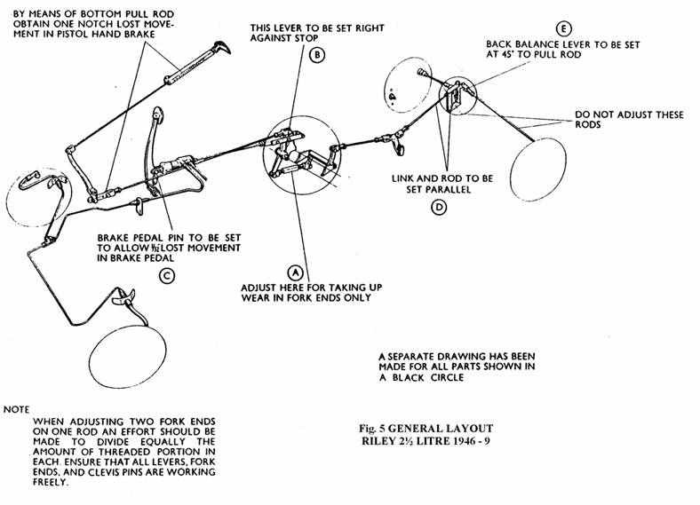
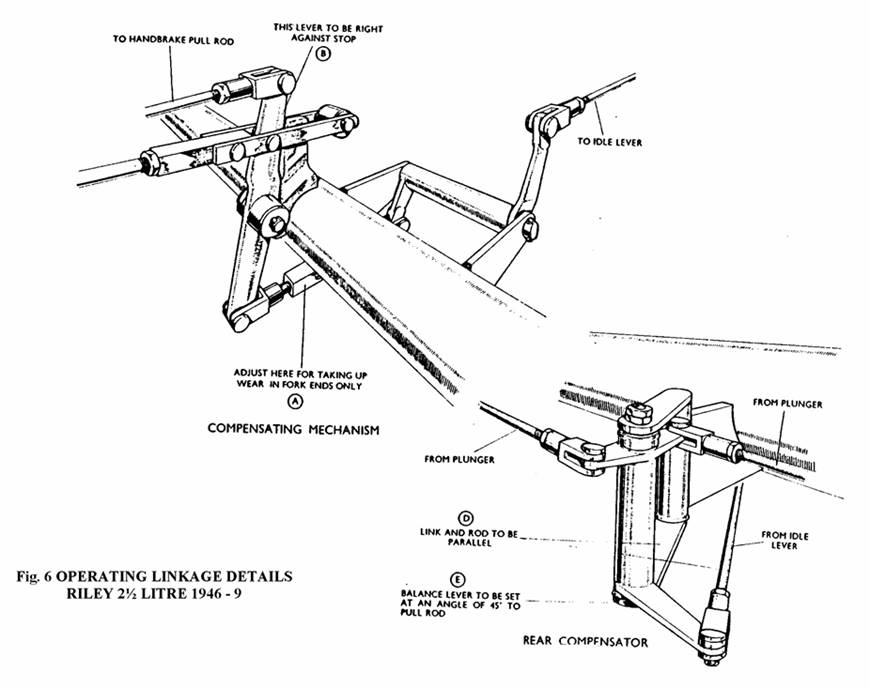
APRIL 1949 TECHNICAL BULLETIN No 45 INSTRUCTIONS FOR THE MAINTENANCE AND OVERHAUL OF GIRLING HYDRO-MECHANICAL BRAKES AS FITTED TO THE RILEY 2½ LITRE DESCRIPTION The brakes fitted to the 2½ Litre Cars are Girling Hydro-Mechanical. This system is a means by which the front brakes are hydraulically operated and the rear brakes mechanically actuated. The Master Cylinder is located in a direct line in such a way that all pedal effort is effectively used, and the failure of either front or rear brakes does not put the pedal out of action, but leaves one pair of brakes in operation, which enables the driver to make a safe stop. METHOD OF OPERATION (Fig.5) The Master Cylinder is connected to the pedal by a slip link. When pressure is applied to the pedal, the cylinder is pulled forward. This causes the plunger in the cylinder to displace the fluid and operate the front brakes, the rear brakes being operated at the same time by the pull rod which is screwed into the rear end of the body of the cylinder. The pull is transmitted to the rear brakes via relay levers to the compensating unit mounted on the rear axle casing to which is connected the brake draw links from the rear brakes. The jaw connecting rod from the Master Cylinder to the relay lever carries a roller. In the unlikely event of a failure on rear brakes due to broken or damaged rods, this roller contacts the stop on the chassis cross- member, thus arresting any further forward movement of the Master Cylinder body. The remaining pedal travel maintains hydraulic operation of the front brakes. Should a failure occur in the hydraulic system, the plunger in the master cylinder travels forward until it contacts an internal stop at the end of its stroke in the cylinder. The cylinder is then in effect a solid unit and the remaining pedal travel maintains mechanical operation of the rear brakes. FRONT BRAKES (Figs 1 and 2) These are Girling Hydraulic. On the earlier models the brakes were 12"x 1.656" Hydraulic Non Servo (Fig.l) Dealing with this earlier type first - The shoes are operated by a hydraulic cylinder of simple construction consisting of two pistons, on which the shoes locate, separated by a light compression spring and two pressure seals. A bleeder valve is incorporated on the top of each cylinder, a rubber cover being fitted to exclude dust, etc. Rubber covers are also fitted over the ends of the cylinder for the same purpose. The shoes are anchored at the bottom of the brake on a pivot and located on the hydraulic cylinder at the top of the brake, being held in position by two springs from shoe to shoe, the stronger spring being fitted at the pivot ends. Adjustment is effected by jacking each wheel in turn, spinning the wheel partly rotating the hexagon Adjustment Bolts which are to be found on either side of the brake cylinder until the brake shoes just come in contact with the brake drum, then slackening back until the wheel rotates freely and without drag. The Adjustment Bolts operate snail type cams, bearing against the shoes. They are frictionally held and require no locking device, and they can easily be rotated with a spanner into the desired position. To bring the shoes closer to the drum, the Adjustment Bolts should be rotated clockwise. To bring the shoes away from the drum they should be rotated anticlockwise, with a spanner on the nut. The later models are fitted with Hydraulic Leading Shoe Brakes (Fig.2). Each of these are operated by two hydraulic wheel cylinders of simple construction, located on opposite sides of the backplate. Each cylinder is fitted with ONE piston and the rear end of the body casting carries a locating spigot to form an abutment for the fixed ends of the shoes. Thus each shoe is located on one cylinder and expanded by the piston in the other, and the leading edges of BOTH shoes make an initial contact with the drum, resulting in highly increased efficiency, and more even lining wear. The brake shoes are held in position by two springs from shoe to shoe, and adjustment for lining wear is effected by two eccentrics bearing against the spring posts. Rubber dust covers fitted over the wheel cylinders completely exclude all dirt and dust from the hydraulic system and the two wheel cylinders are interconnected by a metal pipe outside the backplate, provision being made for bleeding the system. The exploded view clearly shows all details of a typical H.L.S. brake assembly, and also the component parts of the wheel cylinders. It will be observed that the constructions of these latter is extremely simple, consisting of a housing with a highly finished internal bore, in which is assembled a light spring, a seal, a piston and a dust cover. The internal parts can be easily withdrawn when the dust cover is removed. The bleed nipple screw bears upon a steel ball, which is normally seated firmly on a valve opening in the cylinder. Only when the bleed screw is partially released can fluid escape. REAR BRAKES (Fig. 3) The rear brakes are Girling 12"x 1.656" Non-Servo. The shoes are mechanically operated by the expander unit, consisting of a hardened steel cone which is actuated by the brake pull rod and causes two plungers to move outwards. Hardened steel rollers are interposed between plungers and cone to reduce friction to a minimum. The plungers engage directly with the brake shoes. The whole expander mechanism is enclosed in a diecast housing which contains a supply of lubricant. This housing is slidably attached to the backplate by studs and spring washers which provide a slight frictional contact. The housing is free to float to a certain extent, the Simmonds nuts on the spring washers being one turn slack. In view of this it will be seen that the shoes are self-centring. Adjustment for lining wear is made by the brake shoe adjuster. This consists of a hardened steel cone, the spindle of which is screwed with a fine thread and is carried in a steel housing which is spigoted and bolted firmly to the backplate. On the outside end of the cone spindle are machined flats, which enable a spanner to be used, and on its inner face four flats of a predetermined depth are cut. The cone engages two plungers, also with a bearing in the housing, which have inclined faces. On the outer end of these plungers grooves are formed in which the brake shoes are located. For adjustment rotation of the cone in a clockwise direction causes it to move inwards forcing the plungers apart, and expanding the fulcrum end of the brake shoes. The adjuster should be tightened up until a resistance is felt and then slackened one full notch or two clicks. THE MASTER CYLINDER (Fig. 4) This is the GIRLING tension type master cylinder and is not fixed to the chassis but is carried in the operating mechanism, of which it forms an actual link. The earlier type assembly consists of a cast iron housing into which is assembled the plunger, complete with return spring, washer and spring cover, sleeve, recuperating seal, outer seal, seal spreader, seal retaining spring and washer. The whole is protected from dirt and dust by a rubber dust cover packed with Wakefields Rubber Grease Number 3. DISMANTLING Before removing the master cylinder for dismantling it is advisable to drain off most of the brake fluid by disconnecting one of the flexible brake pipes on the front wheel backplate. lowering the open end into a clean container and pumping the brake pedal until no further fluid enters the container. Reconnect the flexible hose. Disconnect the two pipe unions on the side of the master cylinder, and the master cylinder from its connections to the pedal lever and relay lever. The master cylinder can now be removed. Remove the jaw end, lock nut and the rubber boot. Unscrew the three set screws holding the rear half of the cylinder to the forward or pressure end. Remove plunger complete with return spring washer and spring cover, sleeve with rubber sealing ring, seal retaining spring, seal retaining washer, seal spreader and lastly the outer seal. Carefully examine all parts, and replace any that appear worn or distorted. It is especially important that all seals which appear worn or lack resilience should be replaced. ASSEMBLING - First Model. After thoroughly cleaning all parts with clean brake fluid place the outer seal with lips uppermost in the forward end of the cylinder, next the seal spreader with apex towards seal, and seal retaining washer. Assemble the plunger with return spring, washer, spring cover and seal retaining spring and insert into the forward end of the cylinder, taking care not to disturb the seal retaining washer, etc. Screw on the lock nut to the plunger rod, refit rubber boot packed with Wakefields Rubber Grease No 3, screw on the jaw end. Replace the recuperating seal, after smearing with clean brake fluid, with lips facing the forward end of the cylinder. It will be noticed that the sleeves have grooves cut in the centre bore, these are deeper cut one side than the other. It is important that the shallow side is placed next to the recuperating seal, with rubber sealing ring attached. Screw on the rear end of the cylinder with the three set bolts, tighten securely. Second Model. A later assembly introduces a modified sleeve at the back of the recuperating seal. The difference between this sleeve and the old type is the drilled holes through the sleeve, instead of grooves on the inner bore. This change necessitates a protective shim for the back of the rubber seal. This shim must always be placed between the sleeve and the recuperating seal. To allow for the extra thickness of this shim the cylinder body is bored deeper. It will be noticed therefore that the bodies are not interchangeable. Note No.l and No.2 assemblies are interchangeable as complete units, but under no circumstances must the new sleeve and shim washer be fitted to No.l assembly. Third Model (Fig.4) A still later assembly introduces a further addition in the form of a spring washer fitted between the lips of the seal to prevent excessive tilting of the seal. The body is again bored deeper than No.2 assembly to allow for this spacer. It is important to note that this spacer will not fit No.2 assembly. NOTE. All three assemblies are dismantled and assembled in exactly the same way bearing in mind the relative positions of additional items as already described. HANDBRAKE. This is the Girling Pistol Type control and operates on the rear wheels only. Adjustment for lining wear should be made on the brake adjusters and not on handbrake hook up as this is correctly set at the works. The rear brakes should not be allowed to run for long periods without adjustment. An indication of rear brakes requiring adjustment is given when undue travel is felt at the hand brake control before the shoes contact the drums. RUNNING ADJUSTMENTS AND GENERAL MAINTENANCE. Girling brakes are adjusted for lining wear only at the brakes themselves and on no account should any alteration be made to the operating linkage for this purpose. FRONT BRAKES. Jack up the car until the front wheel to be adjusted is clear of the ground and then fully release both hexagon head adjuster bolts on the brake backplate. Turn one of the adjuster bolts in a clockwise direction until the brake shoe is just clear of the drum and then repeat the procedure for the second adjuster, since on the front brake a separate adjuster is provided for each shoe. Spin the wheel to ensure that the brake shoes are quite free of the drum and repeat the adjustment for the other front wheel. The adjusters operate snail type cams which bear against the shoes on some models but against the spring pegs on others. The cams are frictionally held in position and thus require no locking device. To expand the shoes the adjusters must always be turned in a clockwise direction. REAR BRAKES Adjustment is made by turning the square head adjuster on each rear brake backplate in a clockwise direction until a resistance is felt. The adjuster must then be slackened back two clicks. One common adjuster is provided for both shoes in the rear brake assembly and the adjustment of both rear wheel brakes is identical. After adjustment the brake pedal should be applied hard two or three times to centralise the shoes. Again if replacement brake shoes have been fitted the adjuster should be released an additional amount allowing for expansion of the brake linings. Three clicks instead of two should be sufficient until the brake shoes have "bedded" down, when the brakes must be readjusted. REPLENISHMENT OF HYDRAULIC FLUID. Inspect the Supply Tank at regular intervals and maintain about three quarters full by the addition of Wakefield Girling Crimson Brake Fluid. IMPORTANT - SERIOUS CONSEQUENCES MAY RESULT FROM THE USE OF INCORRECT FLUID AND ON NO ACCOUNT SHOULD ANYTHING OTHER THAN THE ABOVE BE USED. Great care should be exercised when adding brake fluid to prevent dirt or foreign matter entering the system. FITTING OF REPLACEMENT SHOES At some time during the life of the car it will be necessary to fit replacement brake shoes, and the following instructions, compiled from service experience, "should be carefully read and followed in sequence of operations.. FRONT BRAKES To remove the old shoes, first jack up the car and place chocks the rear wheels. Remove the wheel and the three brake drum securing screws. Lift off the brake drum. Where the Hydraulic Non Servo Brake is fitted (Fig.l) ease the pivot end of one shoe out of its pin register, when the shoe springs can easily be disconnected and both shoes removed. It is advisable to prevent the two hydraulically operated shoe plungers from expanding by holding these in position with an elastic band placed round the cylinder. Assemble the replacement shoes with the springs facing the backplate, making sure that the weaker spring is at the expander end of the shoes. Refit the operating end of the two shoes into their respective positions on the hydraulic plungers, the brake shoe steady posts and the pivot ends of the shoes should be smeared with Girling Brake Grease before the replacement shoes are fitted. Adjust the brake shoes as described earlier. Where the later brake is fitted, Hydraulic Leading Shoe (Fig.2) to remove the old shoes, first jack up the car and place chocks behind the rear wheels. Remove the wheel and the three brake drum securing screws and screw the two brake adjusters anticlockwise to ensure that the shoes are quite clear of the drum. Lift off the brake drum. Ease the pivot end of one shoe out of its pin register on one of the hydraulic cylinder housings when the shoe springs can be easily disconnected and both shoes removed. It is advisable to prevent the two hydraulically operated shoe plungers from expanding by holding these in position with an elastic band placed round the cylinders. Assemble the replacement shoes with the springs facing the back plate and refit the operating ends of the two shoes into their respective locations on the hydraulic plungers. Note that the springs are handed for off-side and near-side shoes. Then ease the pivot ends of the two shoes into their pin registers on the hydraulic shoe housings. The brake shoe steady posts, and the pivot ends of the brake shoes should be smeared with Girling Brake Grease before the replacement shoes are assembled. Adjust the brakes as described earlier. REAR BRAKES 1. Jack up the car and remove the road wheels. 2. Remove brake drums. 3. To dismantle the brake all that is required is a large screwdriver. It will be found quite easy to prise one shoe out of the groove in the expander tappet. Both shoes and pull-off springs can now be removed, leaving the expander and adjuster units in position on the backplate. Do not detach these units from the backplate and do not over stretch shoe pull-off springs when removing shoes. 4. Clean down backplate, check expander unit for free float on the backplate. THIS IS IMPORTANT. Check adjuster unit for easy working and slack back (anticlockwise) to the full "OFF" position. Lubricate where necessary with Girling Brake Grease. Inspect shoe pull- off springs and replace if stretched or damaged. 5. To fit replacement shoes, fit new springs to new shoes and be sure that the springs are between shoe webs and backplate, otherwise shoes will not be flat on backplate. Keep all grease off linings and do not handle linings more than necessary. Place shoes with springs attached against the backplate. The shoes have half-round slots at one end. Fit these slots to the ADJUSTER LINKS, then insert other end of ONE SHOE in the EXPANDER TAPPET. Place the screwdriver under the web of the remaining shoe. Ease the shoe into the tappet groove. 6. Refit drums - be sure these are clean and free of grease, etc. 7. To ensure correct clearance between shoes and drums, slack off set pins that hold adjuster unit to backplate (not more than one complete turn) and lock up the brake shoes in the drum by turning the adjuster wedge spindle TWO CLICKS, which can be felt and heard. Give the brake pedal a firm application to ensure that the shoes have centralised at the expander end. Drums should now be quite free. Adjuster wedge spindle in a clockwise direction. Screw up adjuster set pins tightly and slack off the adjuster wedge spindle TWO CLICKS which can be felt and heard. Give the brake pedal a firm application to ensure that shoes have centralised at the expander end. Drums should now be quite free. 8. Refit road wheels and jack down. 9. When fitting replacement shoes ALWAYS fit a NEW set of springs. The operation of fitting Girling replacement shoes is now completed, nothing further is required and the car is now ready for the road. Always fit "GIRLING FACTORY LINED" replacement shoes. These have the correct type of lining, properly riveted and accurately ground to size which ensures a fast and easy bed-in to drums. BLEEDING THE HYDRAULIC SYSTEM Bleeding is necessary at any time a portion of the hydraulic system has been disconnected, or if the level of the brake fluid has been allowed to fall so low that air has entered the master cylinder. Always use GIRLING CRIMSON BRAKE FLUID for the hydraulic system since this fluid has been specially prepared and is unaffected by high temperatures or freezing. NEVER TOP UP THE SYSTEM WITH ANY OTHER FLUID. With all the hydraulic connections secure and the supply tank under the bonnet topped up with fluid, slacken off all the front brake shoe adjusters as far as they will go. Remove one of the rubber covers from a front brake bleed nipple and fit the bleed tube over the bleed nipple, immersing the free end of' the tube in a clean jar containing a little brake fluid. Unscrew the bleed nipple about three-quarters of a turn and then operate the brake pedal with slow, full strokes until the fluid entering the jar is completely free of air bubbles. Then, during a down stroke of the pedal, tighten the bleed nipple, remove the bleed tube and replace the bleed nipple dust cover. This process must now be repeated on the opposite wheel. Always keep a careful check on the supply tank during bleeding since it is most important that a full level is maintained. Should air reach the master cylinder from the supply tank the whole of the bleeding operation will have to be repeated. After bleeding, top-up the supply tank to its correct level of approximately three-quarters full, and adjust the front brakes as previously described. Never use fluid that has just been bled from a brake system for topping-up the supply tank since this fluid may be to some extent aerated. Such fluid must be allowed to stand for at least a few hours before it is used again. This will allow the air bubbles in the fluid time to disperse. Great cleanliness is essential when dealing with any part of the hydraulic system and especially where the brake fluid is concerned Dirty fluid must never be added to the system. GENERAL ADVICE ON HYDRAULIC COMPONENTS ALWAYS exercise extreme cleanliness when dealing with any parts of the hydraulic system. ALWAYS use clean brake fluid or alcohol for cleaning internal parts of the hydraulic system. On no account should petrol or paraffin be allowed to contact these parts. ALWAYS examine all seals carefully when overhauling hydraulic cylinders, and replace with genuine Girling seals, any which show the least sign of wear or damage. ALWAYS take care not to scratch the highly finished surfaces of cylinder bores and pistons. ALWAYS use Wakefield Girling Crimson Brake Fluid, obtainable from all Girling Service Agents or direct from the manufacturers Messrs. C.C.Wakefield Ltd. IMPORTANT: If it is suspected that incorrect fluids have been used, ALL SEALS in the Master Cylinder and Wheel Cylinders must be changed after the components and pipelines have been thoroughly flushed out with alcohol or clean Girling Crimson Brake Fluid. NEVER USE PETROL OR PARAFFIN FOR THIS PURPOSE. If the incorrect fluid has been in the system for any length of time, it is advisable to replace the high pressure hoses to the front brakes. OPERATING LINKAGE. This linkage is carefully set by Messrs. Riley Ltd. before the vehicle leaves the Works, and should not normally be interfered with unless replacement parts are necessary, or a complete overhaul of the braking system is required. When carrying out this work, the following instructions should be carefully followed. GENERAL LAYOUT (Fig.5 and 6) 1. Detach compression fork from the relay lever. (A, Fig.6) 2. Lock up rear brakes in the drum by means of the adjuster. 3. Relay lever to be set right against the stop on the cross-member (B, Fig.6) and brake pedal pin (C Fig.6) to be set to allow 1/32" lost movement in brake pedal with the pedal against its stop. 4. The rear longitudinal rod and link to be set parallel (D Fig.5 & 6) and the back balance lever to be set at 45 degrees to the pull rod (E Figs 5 & 6). 5. With the rear shoes still expanded in the drums, the compression link (A Fig.6) must be adjusted so that the clevis pin can be inserted by hand. 6. Obtain one notch lost movement in the hand brake by means of the adjustment on the bottom pull rod (F Fig.5). 7. Adjust the rear brakes as previously described. The car is now ready for the road. NOTE. It is most important that the clearance in the brake pedal is strictly adhered to. |