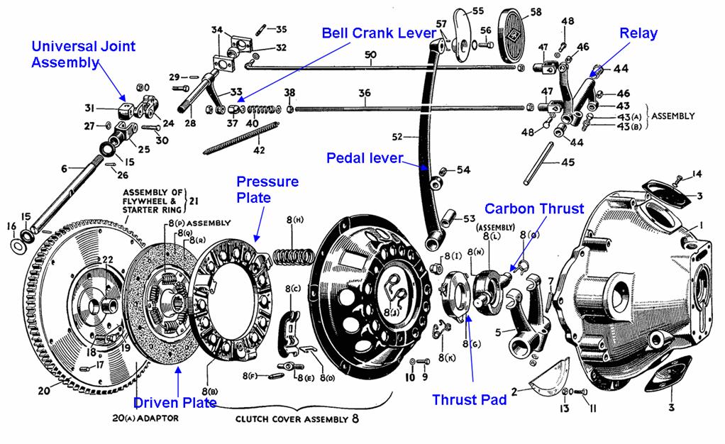
The need for a clutch overhaul is usually indicated by the clutch slipping under heavy load. This can be due to a number of causes including poor adjustment, oil on the clutch facings and wear of the clutch facings. Whatever the cause it should be attended to immediately. If the clutch facing are worn out they will be worn down to the level of the rivets holding them onto the driven plate. The rivets will score both the flywheel face and the pressure plate face making the whole job much more complicated and expensive than it need be. However, before looking at how problems can be overcome it may be worthwhile reminding ourselves of the details of the clutch mechanism. The illustration below shows the main elements in exploded form.
The pedal lever is connected to the top lever of the relay assembly by the rod marked 50. As the pedal is pushed forwards so the top lever of the relay assembly is pulled forwards and the lower lever of the assembly moves backwards. The lower lever is connected to the rod marked 36 and this in turn is connected to the lower end of the bell crank lever marked 33 which is then pulled backwards. This causes the clutch operating extension shaft (marked 28) to twist. The extension shaft is connected via a universal joint assembly to the main clutch operating shaft (marked 6) inside the aluminium clutch housing (the aptly named bell housing). The clutch operating fork (marked 5) is locked in position on the operating shaft by a cotter pin and holds the carbon thrust assembly in its forked ends. Thus the final effect of depressing the clutch pedal is to push forward the carbon thrust bearing.
Not shown in the above illustration but running through the centre of the clutch is the gearbox input shaft. The front end of this goes into the bushed marked 22 in the middle of the flywheel. The shaft is therefore firmly supported at both ends of the clutch. The forward end of the gearbox input shaft is splined and the clutch driven plate (friction plate) slides on these splines so that it turns with the shaft but is free to slide along it. The forward face of the driven plate bears against the flywheel face while its back face bears against the pressure plate. Heavy coiled springs between the pressure plate and the clutch cover push the pressure plate forwards so that it camps the driven plate against the flywheel. Levers connect the pressure plate to the thrust pad so that when the thrust pad is pushed forwards by the carbon thrust bearing the levers pull the pressure plate back thus releasing the driven plate from its clamping effects. When the pressure plate clamps the driven plate to the flywheel, the flywheel and hence the crankshaft is directly connected to the gearbox input shaft so that the two rotate as one. Realising the clamp breaks the direct connection and the engine can turn free of the gearbox.
We can now look at the causes of clutch problems and their cures.
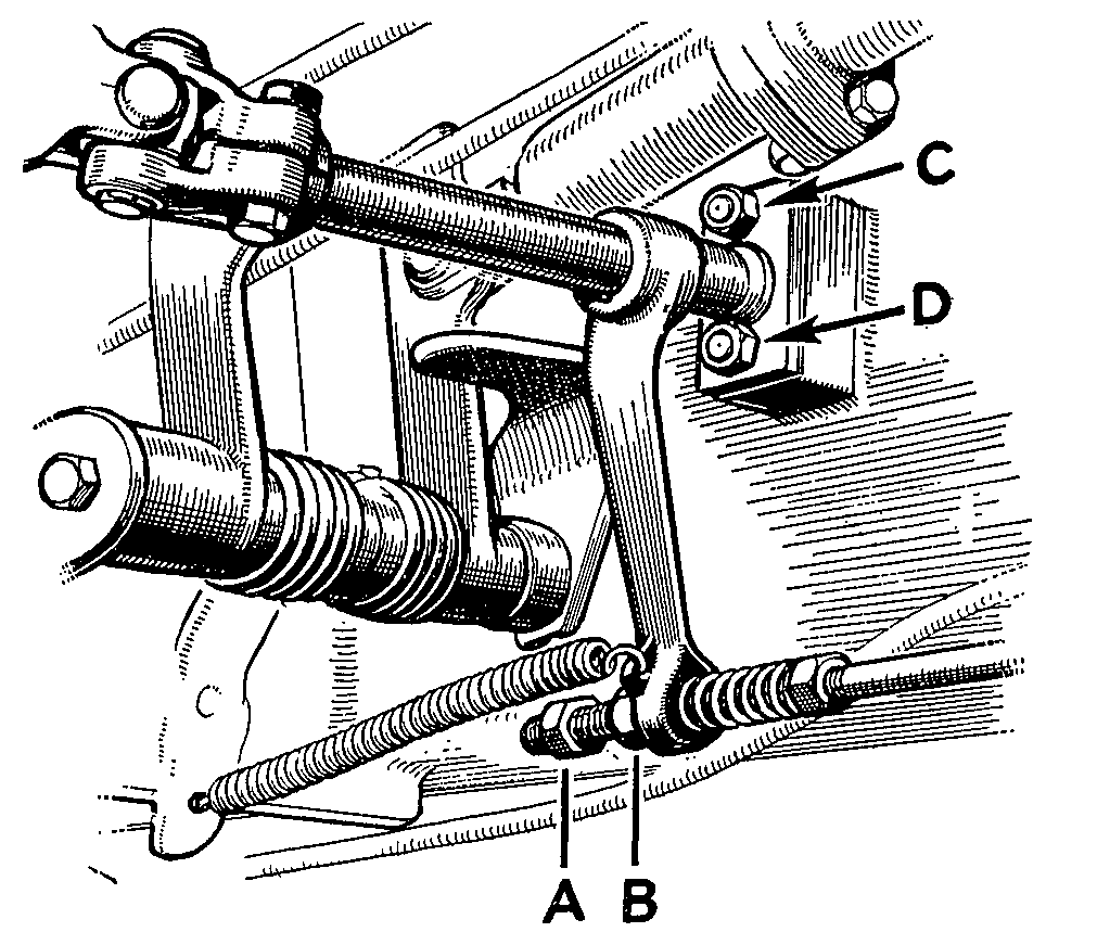
The first thing to do is to check the adjustment. Look under the car just behind the pedals and you will see the adjuster illustrated. Holding the lower end of the bell crank by the nut B, it should be possible to pull the crank forward a little way before positive resistance is felt. This may be easier to do if the return spring is first removed from the crank. This free play should be in the region of 1 to 2 mm. If in doubt, screw the locknut (A) and the adjusting nut (B) forward along the rod to give a lot of free play. You should now be able to move the bottom of the bell crank forwards and backwards easily. Using just finger pressure, hold the crank as far back as it will go, screw the adjusting nut towards it stopping about 1 to 2 mm. before it hits the crank. You should now have the right amout of free play. Finally screw the locking nut up to the adjusting nut and tighten them together making sure that the adjusting nut does nut move. If you found that there was little or no free play before you adjusted it you might just have cured the problem so give the car a road test.
If this has not cured the problem then it must lie within the clutch housing itself and this means taking out the clutch and gearbox. To do this it is not necessary to remove the engine as the clutch and gearbox can be removed from inside the car. The front seats including the panel between the seats and carpets need to be removed together with the front floor boards, the gearbox cover and removable centre panel of the toe board. If there is a centrally mounted heater that will also have to be removed. You should now be able to see all around the gearbox and the bell housing. Although not strictly necessary it can make access easier if the gearbox lid and stick are removed but before doing this check the oil level in the gearbox. A low level may indicate a failed seal. When doing this make sure that the three detent springs and balls at the rear under the gearbox lid do not get lost. The springs can be lifted out and balls can be kept in position by filling the holes left by the springs with grease. You may also want to drain the oil from the gearbox to prevent spillage later.
The universal joint coupling the front of the short propshaft to the gearbox must be undone. It is held by 4 nuts and bolts and to gain easy access to the lower ones jack up one of rear wheels and turn the shaft to bring them to the top. The front of the shaft can now be lifted to one side out of the way and the rear wheel lowered.
The gearbox to body mountings also hold up the rear of the engine so place a wooden block to act as a load spreader under the rear of the sump and support it on a jack. It is possible that you will need to leave this support in place for some while so it is better to use a screw type jack than a hydraulic one which might creep.
The various items which connect to the gearbox and clutch can now be removed. These include the speedometer cable, the restraining cable (right at the bottom of the gearbox on a 1� litre car), the reversing light cable and the clutch operating shaft. To release the clutch operating shaft remove the clevis pin from one of the joints pivot pins and try tapping out the pin. If the pin moves a little way and then stops try removing the other pin. One pin has to be removed first as it locks the other in place. And it is not easy to see which one has to be removed first. Once a pin has been removed the joint will come apart releasing the shaft coupling.
Before undoing the bolts holding the gearbox to the chassis, place a trolley jack under the gearbox locating it under the drain plug. Raise the jack slightly to take the weight off the mounting bolts, undo the bolts and remove them. Raising the jack further should lift the gearbox clear of the mountings to give room to remove it. If it does not it will necessary to remove the mountings completely from both the gearbox and the chassis. As the gearbox is lifted by the trolley jack the jack under the sump should also be raise to continue supporting the engine.
At the bottom of the bell housing on the engine side is an aluminium plate (marked 2 in the main illustration) which must be removed. It is held in place by 4 nuts and bolts.
The starter motor must be released from the bell housing and laid to one side. The bolts holding the bell housing to the back of the engine can now be removed. Finally check that everything attached to the gearbox and clutch has been released so that it can be lifted out cleanly.
Pull the gearbox and bell housing assembly backwards moving the trolley jack with it to provided support. As the gearbox input shaft comes out you will need to lift the rear of the gearbox. Once the shaft is clear of the clutch housing assembly the gearbox and bell housing can be lifted out of the car.
The gearbox and bell housing assembly is heavy particularly on the 2� litre car so support it on a jack while you are getting ready to lift it out of the car and be careful of your back at all times. A strained back takes longer to repair than a clutch!
Now have a look inside the bell housing. You will see the carbon thrust bearing and the fork holding it which is attached to the operating shaft. The inside of the housing will probably be dirty but it should not be running with oil.
Climbing back inside the car, the ring of bolts holding the clutch cover assembly to the flywheel can be undone. These should be released a few turns each at a time to avoid any risk of distortion to the cover. The cover is located on the flywheel by 2 dowels and these may stick in the cover. It is easy to slip a screwdriver between the cover and the flywheel to easy them out but be careful as the clutch cover assembly is heavier than it looks and the driven plate will try to slip out and fall on the floor.
It is now time to check where the problem lies. If the driven plate and everything else is covered with oil there is clearly an oil leak somewhere. There are only two ways that oil can get into the clutch, from the gearbox or from the engine. Oil leaks from the back of the engine are rare. There is no oil seal as such at the back of the crankshaft, instead it uses a scroll and thrower. These work well unless the rear main bearing is badly worn. It is also possible that the main bearing housing has not been properly sealed to the engine block but again this is rare. The gearbox uses a conventional lip seal and this will wear out eventually so is the most likely cause of an oil leak and is almost certainly the cause of the problem if oil level in the gearbox was low. It is often possible to see where the oil has come from. If the gearbox input shaft is covered in fresh oil it is almost certainly from the gearbox seal while oil running down the back of the engine block tells its own story.
Now look at the driven plate. If the facings have worn down to the rivets or are soaked with oil, the plate is of no further use and a new one will be needed but do not throw the old one away just yet. Only very rarely will it be sensible to reuse the old plate. If it has been allowed to wear down to the rivets and beyond check for scoring to the flywheel face and pressure plate face.
The clutch cover assembly which includes the pressure plate, the main springs, the levers, the thrust pad and the cover itself are usually fit for further service once it has been cleaned up provided the pressure plate face is not scored. If the face of the thrust pad is scored it may be possible to find a used replacement in good condition which can easily be fitted. Contrary to often expressed opinions, these assemblies hardly ever wear out but seem to go on for ever. I have two in use at the moment both dating from 1939 and both working well.
If you do need to buy a new clutch cover assembly make sure that it really is the same as the old one. A 2� litre owning friend recently bought a new assembly from a well known source and having fitted it found that the clutch operation was uncomfortable heavy even with his huge boots. I tried it and found the same so we checked out all the linkages and they were spot on. There was nothing else to do but take out the clutch again. We compared his new assembly to an old one I had by placing them both on the floor with the pressure plate downwards. We then put one foot on the thrust plate to release the clutch. We found that the old unit could be compressed with moderate foot pressure but the new unit hardly compressed at all even with a lot of foot pressure. A look at the coiled springs inside the units showed that those in the new unit were thicker than those in the old one. Since the face of the pressure plate was still in good condition in my old unit we reassembled the clutch using that unit after which we found that normal clutch pressure and operation had been restored. So before fitting a new clutch cover assembly put it on the floor next to the old unit and check how much force is needed to depress the thrust plate.
Driven plates for RMs seem be getting expensive but with a bit of work a new plate can be got quite cheaply. Autojumbles are always a good source of cheap spares provided you know what you are buying. Often a trader will not know what a particular item fits and will therefore sell it at well below its retail value to someone who does know. In the case of RM driven plates, very similar items were fitted to many different cars and provided the overall diameter is the same the only significant difference is in the splines in the centre of the plate. Provided the splines are the only difference it is quite easy to remove the splines from the new plate and use the ones from the old Riley
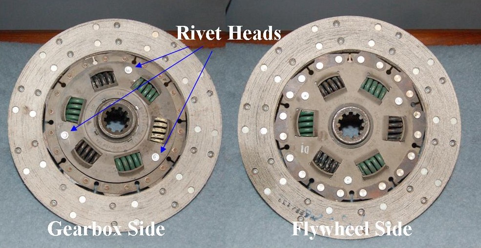
Pictured here are both sides of a 2� type clutch plate, the 1� litre one is very similar. To access the splines, grind the heads off the three rivets indicated on the gearbox side of the plate and lift away the plate covering the 6 springs. Beneath it is a plate to which the splines boss is attached. Lift it away leaving the springs in place. Do the same for the old Riley driven plate and transfer the Riley splined plate to the new one. Replace the covering plate over the rivets making sure that the 6 springs are properly in place. Now, using a welder (arc welding is fine) weld over the top of the rivets onto the cover plate to form new rivet heads. You now have a plate which will fit your Riley just as the old one did but with new facings and new torque reaction springs. If you did not need to change over the splines as you found a driven plate which was stated to be for a Riley, it is worth checking that the new driven plate does indeed fit onto the gearbox input shaft. Sometimes an item which looks right is not right and it is better to find out early than when you are struggling with a heavy gearbox.
Carbon thrust bearings can also be picked up cheaply at autojumbles although old ones too seem to last for ever. They wear much slower than the driven plate friction linings so provided there is 2mm of carbon standing proud from the metal holder it should last until the driven plate needs to be replaced again.
With everything in pieces there is one other thing worth checking. Behind the flywheel in the back of the cylinder block is a core plug. It can only been seen and changed when the flywheel has been removed. Core plugs do not last for ever and it is quite common to find that this one is almost rusted through so now is the time to remove the flywheel and replace it with a new one. If you do not, you know what will happen, a week after the clutch change is finished you will find water dripping out of the bell housing. That will mean taking it all out again just to remove the flywheel and change the core plug
With everything now checked and items replaced as necessary it is time to consider putting things back again.
Aligning the clutch and refitting the gearbox can be difficult particularly if you are working from inside the car.� The gearbox is very heavy and you need to duck under the instruments and glove tray while lifting and aligning everything.� Even with the gearbox supported on a substantial trolley jack it can be quite a balancing act and nothing seems to quite line up.
There is no magic wand which will make the process easy but there are a couple of tips which can make it much easier. It is essential that the clutch plate is accurately centred on the flywheel before the clutch cover is bolted up.� This is easiest done with a clutch aligning tool and it is but a few moments work to make one.� Get a piece of bar (an old wood and rubber valve grinding tool is ideal) and build up the diameter of one end of the bar with sticky tape until it is a good fit inside the flywheel centre bush.� Push it into the bush and the bar should now be sticking straight out from the flywheel.� Slide the clutch plate over it and hold it in place against the flywheel.� Make a mark on the bar to note where the plate splines fit over the bar.� Remove the plate and the bar and again use the sticky tape to build up the bar diameter where� the splines were until the splines are a good fit on the tape
Now slide the alignment tool inside the clutch plate splines checking that it is a tight fit and then insert the tool into the flywheel and push the clutch plate against the flywheel.� The clutch plate will now be properly centred and you can bolt up the clutch cover with confidence.� Tighten the clutch cover bolts progressively and finally check that the bar which sticks out of the cover is still properly centred in the cover.� If all is well, pull out the alignment tool and put it safely away for future use.
Ensuring that the plate is properly centred does not automatically ensure that the splines on the gearbox input shaft will line up with those in the clutch plate.� To make this happen, put the gearbox into gear (top is fine) so that as you turn the output shaft at the back of the gearbox the input shaft also turns.� Now as the clutch slides into place a small turn of the output shaft will bring the splines into alignment.
Of course there still remains the heavy work of getting the bell housing onto the studs, sliding it in at the correct angle and turning the output shaft to align the splines.� This can be made much easier by replacing two of the studs on the back of the engine with longer ones.� The ideal ones to replace are the ones at about 2 o'clock and 10 o'clock and the ideal replacement are old cylinder head studs from a 1� litre engine.� If these are not available, use a length of studding or a long bolt with the head cut off.
Now slide the bell housing onto the long studs, lift and back end of the gear box so that it is square to the flywheel, slide it forwards until the splines try to engage, turn the output shaft a little while continuing to push the gearbox forward gently.� You made need to give the back of the gearbox a little wiggle/shake before everything slides in.
Once the bell housing is on the long studs you can safely let those studs support the front of the gearbox thus keeping your fingers out of harms way and leaving a free hand to line up the back of the gearbox.
With the bell housing safely on the short studs, fit some of the nuts and then unscrew the long studs and replace them the original short studs.� You can now bolt up the nuts tight and refit the gearbox mounting bolts and all the other disconnected items.
Before refitting the floor boards and seats, adjust the clutch for free play. As a final check, jack up a rear wheel and release the handbrake. With the gearbox in neutral make sure that you can turn the prop shaft from inside the car. Now select a gear (top is fine) and again see if you can turn the prop shaft. This time it should be connected through the clutch to engine and should not turn. With it still in gear depress the clutch and see if the prop shaft will now turn. If the clutch is working properly it should turn just a easily as it did when the gearbox was in neutral.
A new driven plate takes time to bed in and compress and until it has it is not uncommon to find that it is necessary to push the pedal down a long way before the plate releases cleanly. This can make it difficult to engage a gear when the car is stationary. If this happens check that the free play is set correctly and make sure that the stop marked 43 in the main illustration is not hitting against the chassis thus limiting the movement of the relay lever. If this does not cure the problem it may be necessary to shorten the rod marked 50 in the main illustration. To do this release the lock nut locking the fork end in position, remove the split pin and the clevis pin holding the fork and screw the fork along the rod thus shortening the rod�s length. Put everything back together and try again. This will allow the pedal the start in a higher position and give it a greater stroke.
The clutch should now release cleanly and you are ready to refit the floor boards and the seat and to give the car a road test.