Fault Finding In The Charging System
Finding faults in the charging system is not difficult but it does require a methodical approach. The test below are extracted from our RILEY RM MAINTENANCE NOTES and will show where the fault lies. To find out how to cure the problem you may need the Notes themselves.
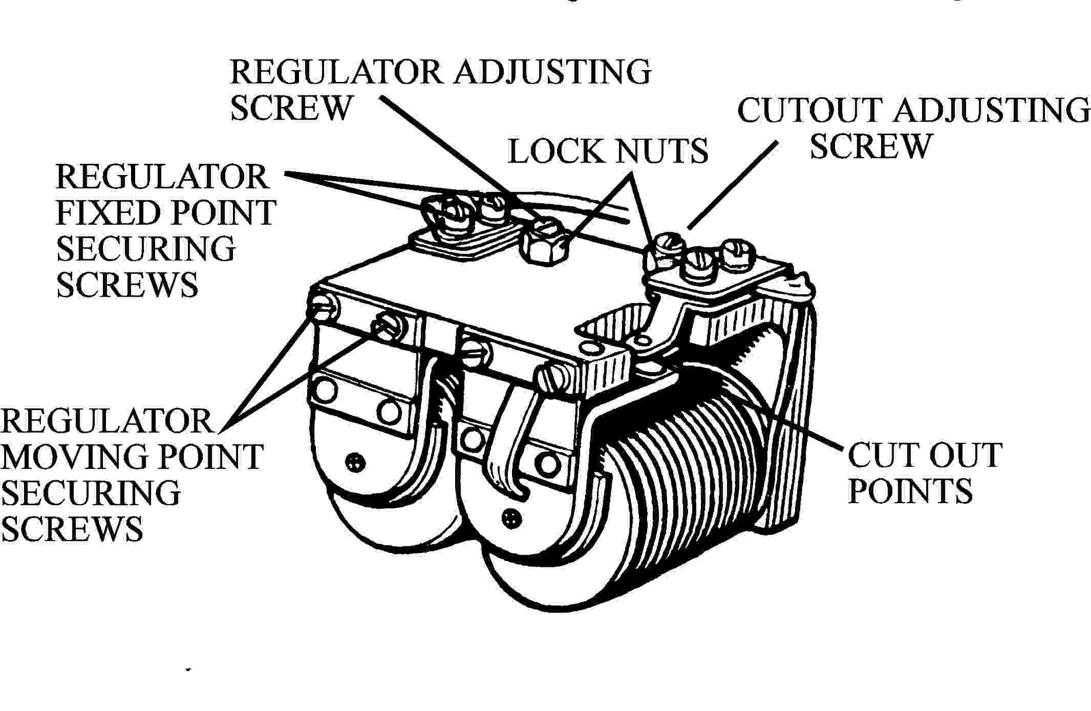
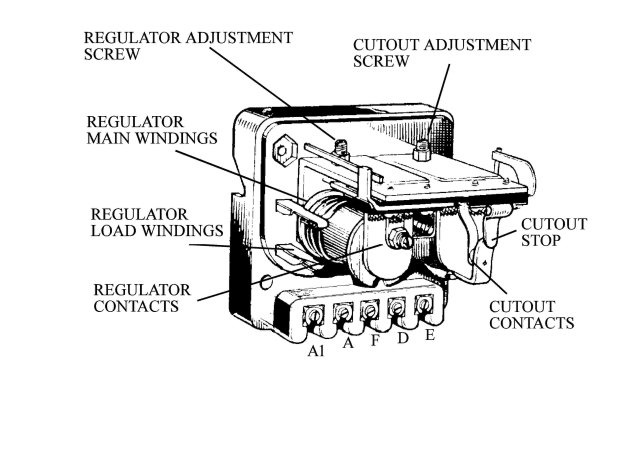
There are two basic types of regulator fitted to RM Rileys and their layouts are shown below. For testing purposes you will need to identify and access the cutout points/contacts.
Step by Step Tests
A voltmeter reading up to at least 20 volts is needed for most of the tests and an ammeter reading up to about 5 amp. is needed for one test. This test (No.2) relates to the dynamo field windings only and can often be omitted. For convenience the cable between the dynamo D terminal and the control box D terminal will be called the D cable and the one between the dynamo F terminal and the control box F terminal will be called the F cable.
Test 1
Disconnect the F and D cables from the dynamo and connect the voltmeter between the dynamo D terminal and a good earth point. Slowly raise the engine speed and note the voltmeter reading.
No reading - check the brushes and clean the commutator. If there is still no reading the armature windings are at fault.
Reading 2-4 volts - Passed. Go to the next Test.
Test 2
Leave the voltmeter connected as for Test 1. Connect the ammeter between the D and F terminals of the dynamo. Raise the engine speed very slowly and note both the ammeter and the voltmeter readings.
Voltage reading of 2-4 volts but no ammeter reading - Break in the dynamo field windings.
Ammeter reading much greater than 2 amp. when the voltage reading is 12 volts - The field windings are shorted to earth.
Voltages rises with speed. When the reading reaches 12 volts, the ammeter reading does not exceed 2 amp. - Passed. Go to the next Test.
Test 3
Reconnect the dynamo cables. Disconnect the D and F cables from the control box. Connect the voltmeter between the end of the D cable and a good earth point. Slowly raise the engine speed and note the voltmeter reading.
No reading - break in the D cable. Uncontrolled voltage, rises quickly with engine speed - Short circuit between the D and F cables.
Reading 2-4 volts - Passed. Go to the next Test.
Test 4
Join together the ends of the D and F cables. Connect the voltmeter to the join and a good earth point. Slowly raise the engine speed.
Reading 2-4 volts - Break in the F cable.
Uncontrolled voltage, rises quickly with engine speed - Passed. Go to the next Test.
Test 5
Leave the D and F cables disconnected from the control box. Connect the voltmeter between the A and E terminals of the control box. Switch the ignition off.
No reading or reading less than the battery voltage - Broken earth cable or poor earth connection to control box.
Reading the same as the battery voltage Passed Go to the next Test.
Test 6
Reconnect all the cables. Connect the voltmeter between the control box D terminal and a good earth point. Place a piece of card between the cutout contacts. Slowly raise the engine speed to 1,500 RPM. Note the voltmeter readings.
Voltage erratic or does not rise with engine speed - control box fault. Remove for overhaul.
Voltage rises with speed and does not stabilise - Fault in the regulator windings or the regulator points are stuck closed Remove the control box for overhaul.
Voltage rises steadily and stabilises at about 16.5 volts - Passed but check the exact reading against the set up data to allow for temperature variations. Go to the next Test.
Test 7
Leave the voltmeter connected as for the previous test. Remove the card from the cutout points. Slowly raise the engine speed and the watch cutout contacts.
Contacts do not move - fault in the cutout windings or the control box internal wiring. Remove for overhaul.
Contacts close outside the range 12.7 - 13.3 volts. Readjust cutout setting.
Contacts close between 12.7 - 13.3 volts Passed. Go to the next test.
Test 8
Connect the voltmeter between the A and E terminals on the control box. Slowly raise the engine speed.
The points move together with increasing engine speed with no reading on the meter or a reading much lower than the regulator setting - The cutout points are not making proper contact. Clean and readjust them.
Cutting in voltage shown on the meter when the cutout contacts close. The voltage then rises to close to the regulator setting Passed, everything is in order.
If you have been thoroughly through the above test you will have located the fault. The Riley Workshop Manual may help you to correct the fault. If not you will either need expert help or our RILEY RM MAINTENANCE NOTES.